Custom Box for Truck; Size constraints - Help & Tips needed

  • 4
    Participant count
  • Participant list

Memnoch

CarAudio.com Newbie
22
3
Texas
Hello, this is my first post here! I am trying to build a sub box for my sons truck. It is his first truck, and we got him his first sound system for Christmas. There is of course size restraints on the box dimensions and I just want to get some feedback before I start cutting anything to build his box. The previous owner had some sort of subs installed, and the wiring is all still intact. The line to the battery is there, the ground is there, and the connections and remote line for the amp are all ran and connected to the deck already. I did purchase a wiring kit though in case but it doesn't look like I will need any of it except for the speaker wire to wire the subs themselves to the amp.

The 2 sealed boxes that the audio place sold us cut out the holes too big, and we won't be able to return them for a while (time and distance from us). So I purchased an 8x4 MDF sheet and the screws, glue etc.. to put one together myself. He would prefer a single box to 2 boxes if that is possible. Details are in the list below for the vehicle and subs etc.

Vehicle : 2001 Dodge Ram 2500

Location in the vehicle: Behind the seats

Space available (Length x Width x Height): 63 1/2" L 8 3/4" W 30" H

Subwoofer make and model: Massive UFO 12" shallow sub

Subwoofer Size: 12

Number of Subwoofers: 2

Type of Port (Kerfed, Slot, Aero, etc.): (unsure)

What type of music do you like?: He listens to pretty much everything but probably heavier on rap

Is your goal SPL or Everyday Music?: Everyday

Tuning Freq (Hz): Unsure

Volume : Unsure

Questions:

Recommended air volume is 1 Cubic Ft per sealed box per 12" sub. The only other recommendation I can find on the spec sheets for the sub is a dual ported box which is 3.11 cubic feet. But the dimensions of that box will not fit his space due to the limited depth of 8.75".

I have come up with a simple rectangle design for the box as follows:

34" long
18" tall
8.75" wide

with the .08 displacement of each sub that would give me roughly 3.13 cubic feet of air space, which is pretty close to the ported recommendations but there is no port on this. Would I add a port or would I need to adjust the dimensions of the box to reduce the air space? Should I add braces inside the box (which would further reduce the cubic space); if so would the dimensions need to be adjusted further?

Would it be better to seal in each sub on the box (ie adding a wall for each sub or a wall between them)?


Please let me know if I am missing anything or if there are any questions. Any help is greatly appreciated!
subbox.JPG
 
Last edited:
That's fine on the amp, once in place you can always upgrade it later, always like to give people options. The stats are very confusing to most. The output is relative to the fuse rating and on brands that claim MAX power instead of RMS as the selling point, it's the way I get that rating. If you take voltage of 14.4 (the industry standard) and multiply it times tha fuse rating of 50A, you will come up with 720 watts. Then multiply that by the amps efficiency of (optimistically) at 80% and you get 576 watts. Knowing the brand, probably closer to 500 - and it will do close to that - hopefully.

The Massive website indicates the following for that subwoofer - they only have the one shallow mount unit and it is a dual 4 ohm voice coil (2) coils on each woofer, each coil is 4 ohms.

1704313213551.png


On any woofer, you can have multiple windings, or voice coils. In your case, that woofer has two and each is wound to 4 ohms. When you wire them altogether to one amplifiers mono output, that amp sees it as a single load. How you wire that is what the amp will read.

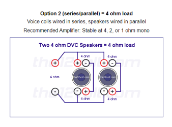
The wiring diagram I gave you is correct for this application, it's a series/parallel configuration.

Wiring any one coil to another in series will give you double the impedance, parallel half. In this case, you are wiring each of the woofers coils in series or each individual woofer. That makes each woofer 8 ohms

1704312584470.png


Then you take the two, now wired to 8 ohm woofers and run the leads together +/+ and -/- (parallel) as one +/- to that amplifier. The amp sees the load as 4 ohms.

Broski probably knows this too, but might not be able to explain it as I have or based on what he perceives he is working with.

Take solace in the fact that most of the responses given in this and any forum are watched and kept in check by multiple people reading the information who usually have no compunction about pointing out if something is amiss, if it were. Might want to just nod your head in the affirmative to the bro-man, keep the family in harmony!
 
Last edited:
That's fine on the amp, once in place you can always upgrade it later, always like to give people options. The stats are very confusing to most. The output is relative to the fuse rating and on brands that claim MAX power instead of RMS as the selling point, it's the way I get that rating. If you take voltage of 14.4 (the industry standard) and multiply it times tha fuse rating of 50A, you will come up with 720 watts. Then multiply that by the amps efficiency of (optimistically) at 80% and you get 576 watts. Knowing the brand, probably closer to 500 - and it will do close to that - hopefully.

The Massive website indicates the following for that subwoofer - they only have the one shallow mount unit and it is a dual 4 ohm voice coil (2) coils on each woofer, each coil is 4 ohms.

View attachment 55865

On any woofer, you can have multiple windings, or voice coils. In your case, that woofer has two and each is wound to 4 ohms. When you wire them altogether to one amplifiers mono output, that amp sees it as a single load. How you wire that is what the amp will read.

The wiring diagram I gave you is correct for this application, it's a series/parallel configuration.

Wiring any one coil to another in series will give you double the impedance, parallel half. In this case, you are wiring each of the woofers coils in series or each individual woofer. That makes each woofer 8 ohms

View attachment 55864

Then you take the two, now wired to 8 ohm woofers and run the leads together +/+ and -/- (parallel) as one +/- to that amplifier. The amp sees the load as 4 ohms.

Broski probably knows this too, but might not be able to explain it as I have or based on what he perceives he is working with.

Take solace in the fact that most of the responses given in this and any forum are watched and kept in check by multiple people reading the information who usually have no compunction about pointing out if something is amiss, if it were. Might want to just nod your head in the affirmative to the bro-man, keep the family in harmony!


thank you that clears it up quite nicely. Looking at the slight wedge box he is building (sealed for each sub) which he has already cut the pieces for, It's looking at roughly 1.31 cu ft per sub side. Silly question, how do you wire the 2 subs together if they are sealed in their own boxes respectively. Do you just connect them at terminals on the outside of the box and then run to the amp? The final wiring diagram is the one you suggest for these subs/amp combo?

Also as I stated, when testing the speaker it was reading at 2 OHM, so does that mean that the speakers may be bad or just not rated to what they should be?


Side note, I went to the garage, measured all of his cuts and built it in sketchup, nothing lines up lol...he's going to be doing some more cutting before he's able to piece that thing together.
 
Last edited:
When you measure both the coils wired in parallel, +/+ and -/- then to the MM, they will read 2 ohms. If you check each coil, +/- to the MM, as one individual coil, they are going to read 4 ohms. If you're using a MM, then it will read DC resistance and be slightly lower, like 1.8 in parallel and 3.7 for each individual coil, or something close to that.

As for his box, he is a good 35% too large. it might be okay but generally, with a sub like these, like to be within 10-20% of the manufactures recommendations.

1704325218464.png


The air in a sealed enclosure acts like a cars spring and shock in one, and helps the woofer control movement in line with the design parameters. Going to large (like double or triple the recommended size) reduces the airs mechanical ability to control that movement and can result in damage to the woofer. Kind of like putting 40" gumbo mudders on a stock truck suspension and not changing the springs or shocks, they (like the air in the enclosure) becomes ineffective at controlling the movement it is there to help with. I don't think that is a huge concern here but it will reduce the effective power use of the woofer. The larger over that 1 cu ft, the more the impact it will have (negatively) respective off that differential.

As for wiring the two in a dual chambered sealed box, you can drill a hole between the chambers and run a wire to both and out to one terminal (a little dab of glue will do ya) or run dual terminals on the outside of the box and wire them together after the fact, what ever suits your fancy!

AS for either the sealed or the ported, the wiring in either instance is the same:

1704326261095.png
 

Attachments

  • 1704326068617.png
    1704326068617.png
    20.6 KB · Views: 13
Last edited:
This tutorial is helpful


Thank you that was super helpful. I am going to get my father in laws MM and measure the subs again, I am pretty sure that when the MM was connected to just one + and one - port on the sub that it was reading 2 OHMs with nothing else connected.

I am redesigning the box as well (well resizing really) as I learned he wants to be able to put his center console up so someone can sit in the middle, and that drastically reduces the space behind the seats. There are also some sort of clips installed on the back wall throughout that add a bit of depth as well so I need to take that into consideration.

I'll post the dimensions etc. when I am finished with it. I think it will still work, it comes out to around 3.62 cu ft with the modifications. I have a couple of questions though about the ports. The spec sheet had said 12" in length and 4.5" from the wall. The ones you suggested for this are 20", and neither those nor a 12" port would be 4.5" from the facing wall. With the 20" it would still be around 22" from the wall. Does that affect performance or air flow? The only other way to try and solve that if it does, would be to build the box taller and reduce the length but I don't know if that would be possible without blocking too much of the rear windshield.

I meant to ask, would each port take up the .25 cu ft of air or was that for both? I assume the brace being open on both ends, and having the center hole would not take up much of the air space, but should the brace run fully along one of the front or back wall or is it fine just in the middle like I have it in the picture below?

And finally, when building the walls, is there a particular order that would be better suited to put it together. The dimensions would change depending. Example. the top and bottom in the one I am working would be the outside pieces, and the current design has the front and sides on the inside of the top and bottom. Would it be better to put the front and back panels on the outside? I would assume it would be easier to mount the front panel last that way, but thought with them on the inside it would provide more structure stability for the bottom.


inside mount.JPG


brace.JPG
 
Last edited:
“I am pretty sure that when the MM was connected to just one + and one - port on the sub that it was reading 2 OHMs with nothing else connected.”

What does the box and the literature sheet say? The massive website only list the one shallow mount sub in a dual 4 ohm configuration.

“I am redesigning the box as well (well resizing really) as I learned he wants to be able to put his center console up so someone can sit in the middle, and that drastically reduces the space behind the seats. There are also some sort of clips installed on the back wall throughout that add a bit of depth as well so I need to take that into consideration.”

As long as you are close to those ideal internal volumes that we’re shooting for, that is the goal. 3.62 is on the large size. need to get it down to around 3.12 – 3.25 gross. 3.6 is too large.

I hate to do this but I’m going to switch gears on you. Let’s consider a port that is rectangle and uses the existing structures front baffle and rear wall.

Taking the internal depth of the box, internally, you have 7.25” instead of using the two round ports; let’s design a slot port up the middle. It will need to be 7.25”D x 3.25”W x 12.875”L.

Make the box get to that golden 3.12 – 3.25 cubic feet. We can add extra pieces of wood internally on the sides, or as braces, etc, we need to get the box to that size., This rectangle port will run up the middle and vent out the top as up and out the top seems the easiest and it allows the port to bounce off the roof, give you a little cabin gain. , here is an example (not to scale, just for orientation sake) Let's stick to the port exiting out the top. In the middle up out the top.


1704344032921.png


This does two things. it simplifies the build ( as all you have to do is cut the hole out the top, cut two pieces to leng and glue them in) and the port now does dual duty as a very strong brace up the middle. In this enclosure, the size is important and the port dimensions need to be as stated. That port in a 3.12-3.25 box gets you to that 33-35 hZ tuning point. That's close to or slightly above the resonant frequency of the driver. With the power that you are givin g this box, that port should be fine. Porting out out the top eliminates obstruction concerns, etc. I modeled it and the vent velocity is marginal.

In this design, I've already taken into consideration the woofer and port displacement, no need to overthink it. I would add corner bracing like this:

1704345147480.png


Anywhere you can, it adds rigidity. It's going to be a fairly stout box with that port running up the middle, no need to worry to much about the minimal displacement adding the corner braces will deduct from the volume, it's insignificant.

Stick to this design, it's a simple, effective, no compromise design - win/win

"And finally, when building the walls, is there a particular order that would be better suited to put it together."

I would build so that the front baffle and the rear baffle are over the sides, not within them. - the opposite way you have your cad drawing.
 
Last edited:
“I am pretty sure that when the MM was connected to just one + and one - port on the sub that it was reading 2 OHMs with nothing else connected.”

What does the box and the literature sheet say? The massive website only list the one shallow mount sub in a dual 4 ohm configuration.

“I am redesigning the box as well (well resizing really) as I learned he wants to be able to put his center console up so someone can sit in the middle, and that drastically reduces the space behind the seats. There are also some sort of clips installed on the back wall throughout that add a bit of depth as well so I need to take that into consideration.”

As long as you are close to those ideal internal volumes that we’re shooting for, that is the goal. 3.62 is on the large size. need to get it down to around 3.12 – 3.25 gross. 3.6 is too large.

I hate to do this but I’m going to switch gears on you. Let’s consider a port that is rectangle and uses the existing structures front baffle and rear wall.

Taking the internal depth of the box, internally, you have 7.25” instead of using the two round ports; let’s design a slot port up the middle. It will need to be 7.25”D x 3.25”W x 12.875”L.

Make the box get to that golden 3.12 – 3.25 cubic feet. We can add extra pieces of wood internally on the sides, or as braces, etc, we need to get the box to that size., This rectangle port will run up the middle and vent out the top as up and out the top seems the easiest and it allows the port to bounce off the roof, give you a little cabin gain. , here is an example (not to scale, just for orientation sake) Let's stick to the port exiting out the top. In the middle up out the top.


View attachment 55883


This does two things. it simplifies the build ( as all you have to do is cut the hole out the top, cut two pieces to leng and glue them in) and the port now does dual duty as a very strong brace up the middle. In this enclosure, the size is important and the port dimensions need to be as stated. That port in a 3.12-3.25 box gets you to that 33-35 hZ tuning point. That's close to or slightly above the resonant frequency of the driver. With the power that you are givin g this box, that port should be fine. Porting out out the top eliminates obstruction concerns, etc. I modeled it and the vent velocity is marginal.

In this design, I've already taken into consideration the woofer and port displacement, no need to overthink it. I would add corner bracing like this:

View attachment 55884

Anywhere you can, it adds rigidity. It's going to be a fairly stout box with that port running up the middle, no need to worry to much about the minimal displacement adding the corner braces will deduct from the volume, it's insignificant.

Stick to this design, it's a simple, effective, no compromise design - win/win

"And finally, when building the walls, is there a particular order that would be better suited to put it together."

I would build so that the front baffle and the rear baffle are over the sides, not within them. - the opposite way you have your cad drawing.


Ok I will redesign and work on it. I did a redesign with the new measurements, still using 2 4" pvc ports, but moved them to where they were at the top and bottom of the side panel. Reasoning is now the internal width has been reduced to 4.5" of space, and the sub depth is 3.11". With it how I originally planned it, the ports would not fit, so now they are above and below the subs for room. But I think the air space is now to low with those dimensions. A sealed box similar to the new design hits the numbers perfect, but I still want to try and fit the port in, so perhaps with a port on top that will be possible, I just need to figure out the dimensions to get the air space right internally. It may not be possible with that width without making it to tall, but I will know shortly.


The spec sheet on the subs state 3.4 on individual ohms 1.7 parallels and 6.8 in series. I've attached a picture of the sheet.

spec.jpg
 
When you get that box to 3.12-3.25, let me know and I will give you the port dimensions. The slot port makes it a lot easier to configure even if the depth changes. As for those readings, they are DC resistance and support my findings of dual 4 ohm coils. RE is the number you want to look at on that sheet. If you only have 4.5" of depth and can get to that 3 cubic feet, the plort would measure 4.5 x 13.5 x 5 Just get me close to that 3.12, we're good to go.
 
Ok, sorry, had lunch with the wife. Here it is final, with the exception of the port.

OD: 61.5" L 22.5" H 6" D
ID: 21" L 60" H 4.5" D

Gives me 3.28 -.08 each sub = 3.12

Will work on port now with what you posted above unless this changes things. If needed I could adjust the length or height an 1" or so more if the air space with the port drops it to much. 22" sides I think would be 3.44 - .16 = 3.28


subredo1.JPG
subredo2.JPG
subredo3.JPG
 
Last edited:
If I understood correctly, this is how you mean with the port? Inner length down is 13". Port opening is 5x4.5


View attachment 55912View attachment 55913
Awsome, that looks like a winner, perfect front/rear baffle orientation and pretty damn thin - crazy! The port is fine as stated previously, 4x4.5 x 12.5-13 gives you around 34 hz and will make for a good stiffening brace and with the depth as short as it is, corner bracing is optional for sure. Looks great!
 
You could even go with a port that is 4.5 x 6 x 15.75 to 16 inches. bigger is better and with the height you have plenty of clearance. Definitely go with the longer wider port. Less noise!
 
Ok, I had to go back to work, I'll adjust it when I get home. The added length on that with it going down won't affect the performance of the subs? That will almost seal them into 2 separate chambers, with only a 5" gap at the bottom.

Ya its crazy thin haha
 
Naw, that is enough clearance. It just seems like it separates it, not really a factor here. Technically, you could run sold braces down to where there was only an inch of clearance, would still be a shared compartment. Ideally, the port should be 1 vent size away from the sides and opposing walls. We are very close and I think that the larger opening with dual 12's is the bigger consideration here. Vent velocity and wind noise get louder as the vent size is reduced. I think that this is a good compromise.
 
Activity
No one is currently typing a reply...

About this thread

Memnoch

CarAudio.com Newbie
Thread starter
Memnoch
Joined
Location
Texas
Start date
Participants
Who Replied
Replies
56
Views
3,254
Last reply date
Last reply from
Memnoch
pattern-wavelength.jpg

winkychevelle

    Apr 27, 2024
  • 0
  • 0
20221010_113336 (5).jpg

audiobaun

    Apr 27, 2024
  • 0
  • 0

Latest topics

Top